The translation stage ‘Standa 960-0060’ sells for $399 and offers a full-step resolution of 1.25 micrometer (200 steps/turn, 250 micrometer per turn). With factor 8 or 16 microstepping, the resolution should be sufficient for interferometric experiments with visible light (156 or 78 nm resolution). The stepper can be easily controlled with an Arduino-based USB controller for a cost of less than $40, but a little soldering is required.
Required Items:
Standa stage 960-0060, e.g. via Eksma, ($399)
Arduino UNO or compatible, e.g. Seeeduino V3.0 or 4.0, $20
Stepper motor driver, e.g.,
Easydriver (8 microsteps), e.g. via Aliexpress ($2.50) or via Sparkfun, ($15)
Alternative: BigEasy driver (16 microsteps), via Aliexpress, ($10) or via Sparkfun ($20)
Power supply, e.g. 12V, 2A, via Aliexpress ($5)(We just use whatever is lying around)
Enclosure, e.g. via Aliexpress, ($3)
A piece of circuit board, some wire and solder, a VGA female socket, some connector pins.
An available Arduino program library ‘AccelStepper’ [http://goo.gl/iCuV7h] offers most functions required to control a stepper motor via the stepper motor drivers mentioned above. It accounts for the steps/direction to track the position of the stepper motor and it accellerates and decellerates the stepper to ensure smooth motion. To connect the required pins from the Arduino to the stepper driver I soldered a shield. But the set-up can be completed in approx. 10 minutes using patch cables. The Standa translation stage is confectioned with a male VGA plug.
(1) Connecting the Arduino and the motor driver
STEP and DIRECTION
The stepper motor drivers mentioned above require a _STEP_ and _DIRECTION_ input. For every 5V pulse on the STEP input, the motor driver performs one (micro-)step. The DIRECTION input controls the motion direction based on a 0 V / 5 V input. Any digital output of the Arduino is suited.
MICROSTEP 1/2/3
The microstep inputs on the driver board control the stepsize for each motor step. Available stepsizes are full step (MS1=0, MS2=0), half step (MS1=5V, MS2=0), quarter step (MS1=0, MS2=5V), and 1/8 step (MS1=5V, MS2=5V). The big eassy driver also offers 1/16 step (MS3=5V, check this value). Warning: Changing the microsteps changes the motion velocity; the same number of steps leads to different motion distances depending on the microstep settings. Any digital output of the Arduino is suited.
ENABLE and SLEEP
The ENABLE and SLEEP inputs on the driver board allow to enter power-saving modes by turning off the current to the stepper motor. (Motor and controller can get very hot when powered, sometimes a matter of concern.) The motor can be manually moved when in either power saving mode. Any digital output of the Arduino is suited. I only attach ENABLE.
POWER and GROUND
I supply the power from the Arduino VIN pin to the stepper driver. Depending on the power supply used to power the Arduino, this can supply up to 15V (limit of the Arduino). I do not know whether a large power draw would overly tax the rather tiny contacts on the Arduino but so far I didn’t have a problem.
(2) Connecting the Arduino to the stepper motor / stage
The translation stage contains two limit switches, NegativeLimit and PositiveLimit, that can be read out via the Arduino. This can be used to ensure that a motion stops before the stage reaches its limit and also to establish a reference position for absolute positioning. Any digital input of the Arduino is suited.Arduino must also supply ground to the stage to allow pulling the limit switches low when the limit is exceeded. I also connect 5V power from the Arduino to the stage, but I believe this stage does not utilize this power (no active sensors or other power-consuming devices in the stage).
(3) Connecting the stepper motor driver to the stepper motor / stage
The stepper driver puts out current to the A and B phases of the stepper motor (A1/A2, B1/B2). Note: If you want to use a power supply with >15 V for the stepper motor, then you cannot run the power through the Arduino. Simply add an power socket to power the stepper driver separately and leave the Arduino powered via USB.
Summary of the connections:
Arduino Easy Stepper Driver
GND —– GND
D2 —– STEP
D3 —– DIR
D4 —– MS1 (microstep 1)
D5 —– MS2 (microstep 2)
D6 —– MS3 (microstep 3, only for A4988 driver)
D7 —– ENABLE
GND —– PWR GND
VIN —– PWR IN
Arduino 960-0060
A1 —– VGA 8 (negative limit switch)
A2 —– VGA 9 (positive limit switch)
960-00060 Easy Stepper Driver
VGA 1 —– MOTOR A
VGA 2 —– MOTOR A
VGA 3 —– MOTOR B
VGA 4 —– MOTOR B
VGA 5 —– +5V
VGA 7,13,14 —– GND
Software
An Arduino program Standa_960-0060_with_EasyDriver helps to track the translation stage position and allows absolute / relative moves in mm units. I programmed the Arduino with a command set resembling that of Physik Instrumente controllers. The program can be downloaded with the link above and requires the following libraries:
SerialCommand_TS // Command library to handle serial commands (via USB)
// Identical to SerialCommand, but case-insensitive.
AccelStepper // Stepper motor motion routine
EEPROM // EEPROM read/write
EEPROM_anything // EEPROM read/write (for saving positions)
Commands with missing arguments are queries
/ denotes alternatives, * indicates argument type
ACC *int: Set accelleration (default 1800 steps/s^2)
DFF *int: Set scaling factor (default 1:mm)
MOV/goto *int: Move to absolute position
MVR/move *int: Move relative to current position
MNL: ! Move to negative limit
MPL: ! Move to positive limit
POS *float: Set (query) current position value
QIT: Prepare for shutdown (move to next full-step position and save position)
REF/GOH: Move to reference position (negative limit)
STP/stop: Stop motion
VEL *int: Set maximum velocity (default 780 steps/s)
VER *int: Toggle verbose answers (default 1:on)
5: Poll motion status
MST *int: Set microsteps (1, 2, 4, default: 8, 16)
HLP: Print a list of commands
*IDN?: Print device identifier
Figure 1: Easy-driver shield and Arduino with digital pins aligned side-by-side. Pins marked with yellow are not used. The 56×80 mm shield was broken out of a larger circuit board to match the size of the housing.

Figure 2: Easy-driver shield and Arduino with analog pins and voltage pins aligned side-by-side. Pins marked with yellow are not used.

Figure 3: Assembled easy-driver shield and Arduino. The patch cable was soldered onto a VGA connector.

Figure 4: Assembled easy-driver shield and Arduino. Pins marked with yellow are not used. All pins were shortened on this side of the board because the housing only offers ~1 mm space

Figure 5: Sliding the easy-driver and Arduino into the housing. The shield pushes the Arduino USB and power jack against holes drilled into the enclosure. The VGA connector is screwed into the other end of the enclosure.
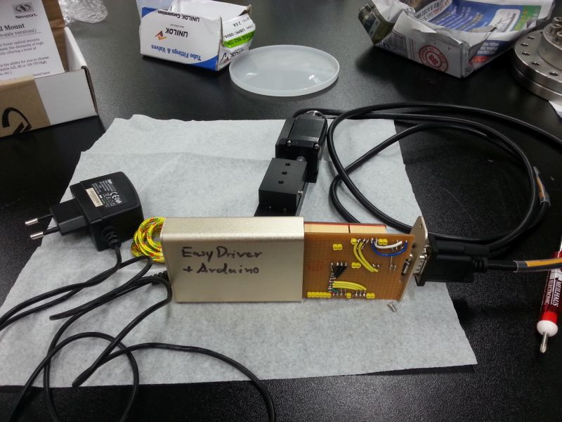
Figure 6: Final assembly. The small 5V power supply is sufficient to move the stepper but a larger power supply may be useful to generate enough torque for microstepping.
